Reference · Use case diagram
Use case diagram examples: 8 worked UML diagrams explained
In short
A use case diagram shows who (actors) can do what (use cases) with a system, and nothing about how or in what order. The eight examples below — ATM, online shop, library, hospital, airline, ride-hailing app, university enrolment and restaurant — each follow UML 2.5.1 notation: stick-figure actors outside a named boundary, verb-first ovals inside, solid association lines, dashed «include» arrows for mandatory sub-goals and dashed «extend» arrows for optional ones. Every example lists its actors, use cases and relationships and explains why it is modelled that way. For the notation rules themselves see the use case diagram reference.
Updated · by the ChartCraft team
What elements does a use case diagram use?
Seven, and the eight examples below use nothing else: actors, use cases, one system boundary, association lines, «include» and «extend» dependencies, and generalization. All are defined in the OMG UML 2.5.1 specification (clause 18, Use Cases).
| Symbol | Name | What it means in the examples |
|---|---|---|
| Actor | A role outside the system that interacts with it — a person, an organisation or another system. Primary actors trigger use cases; secondary actors are called on by the system (payment gateway, maps service). | |
| Use case | A goal an actor can achieve with the system, named verb-first: Withdraw cash. One oval per goal, never per screen or button. | |
| System boundary | A rectangle named after the system. Every use case is inside; every actor is outside. | |
| Association | A plain solid line from an actor to a use case: this actor can perform this use case. No arrowhead. | |
| «include» | A dashed arrow from the base use case to a use case that is always performed as part of it. Arrow points at the included case. | |
| «extend» | A dashed arrow from the optional extension to the base use case it augments under a condition. Arrow points at the base case. | |
| Generalization | A solid line with a hollow triangle from a specialised actor (or use case) to the general one it inherits from. |
How do you read a use case diagram?
Start from an actor, follow its solid lines to the ovals it can reach — that is the actor's complete menu of goals. Then follow any dashed arrows out of an oval: an «include» arrow leads to a sub-goal that is always part of it, an «extend» arrow arrives from an optional add-on. There is no order, no time axis and no data on the page.
| Reading rule | Detail |
|---|---|
| Actors are roles, not people | One person can be two actors (a librarian who is also a member). An external system is an actor too — anything the system exchanges messages with and does not control. |
| Lines mean can, not must | An association says the actor is allowed to trigger the use case. Frequency and obligation are not on the diagram. |
| «include» points at the included case | Base → included. Read: “Withdraw cash always includes Authenticate with PIN.” Removing the included case breaks the base case. |
| «extend» points at the base case | Extension → base. Read: “Print receipt extends Withdraw cash when the customer asks for a receipt.” Removing the extension leaves the base case complete. |
| Secondary actors attach where they are used | The Payment gateway connects to Make payment, not to Checkout, even though Checkout is what the customer sees. |
| Generalization is inheritance | A specialised actor inherits every association of the general actor. Draw it only when the specialised role adds use cases. |
The two-second test for include vs extend, from the use case diagram reference: does the base case always need it? Always → «include». Only under a condition → «extend». Unsure → leave the arrow out.
Example 1: how is the atm use case diagram modelled?
Authentication is an «include» because every transaction needs it unconditionally; pulling it into one use case removes four copies of the same steps.
Include and extend relationships
| From | Relationship | To | Condition |
|---|---|---|---|
| Withdraw cash / Check balance / Deposit funds / Transfer money | «include» | Authenticate with PIN | always — no transaction runs without it |
| Print receipt | «extend» | Withdraw cash, Deposit funds | only if the customer asks for a receipt |
Why it is modelled this way. Authentication is an «include» because every transaction needs it unconditionally; pulling it into one use case removes four copies of the same steps. The receipt is an «extend» because the base use cases are complete without it — it adds behaviour only under a condition. The Bank system is drawn as an actor even though it is software: anything outside the boundary that the system exchanges messages with is an actor. The Technician's two use cases show that one diagram can carry several roles with no overlap.
Example 2: how is the online shopping use case diagram modelled?
The actor generalization (hollow triangle from Registered customer to Customer) is the point of this example: a registered customer can do everything a plain customer can, plus two more use cases, without re-drawing five association lines.
Include and extend relationships
| From | Relationship | To | Condition |
|---|---|---|---|
| Checkout | «include» | Make payment | always |
| Checkout, Track order | «include» | Log in | always — guest checkout would make this an «extend» instead |
| Apply coupon | «extend» | Checkout | only when the customer has a code |
Why it is modelled this way. The actor generalization (hollow triangle from Registered customer to Customer) is the point of this example: a registered customer can do everything a plain customer can, plus two more use cases, without re-drawing five association lines. Log in is shared through «include» by two base cases. The Admin's use case sits inside the same boundary because it is the same system — scope, not user type, decides what goes in the box.
Example 3: how is the library system use case diagram modelled?
Pay fine is the textbook «extend»: returning a book is complete on its own, and the fine step is inserted only under the condition “overdue”.
Include and extend relationships
| From | Relationship | To | Condition |
|---|---|---|---|
| Borrow book, Renew loan | «include» | Verify membership | always |
| Pay fine | «extend» | Return book | only if the book is overdue |
Why it is modelled this way. Pay fine is the textbook «extend»: returning a book is complete on its own, and the fine step is inserted only under the condition “overdue”. Note that the Librarian is associated with Pay fine while the Member is not — the librarian records the payment; the member's involvement is implied through the base use case. Search catalogue has no relationships at all, which is normal: most use cases are plain goals.
Example 4: how is the hospital use case diagram modelled?
Three human roles share one system, so the diagram's value is showing who may do what: a Receptionist bills but never diagnoses.
Include and extend relationships
| From | Relationship | To | Condition |
|---|---|---|---|
| Book appointment | «include» | Check availability | always |
| Bill patient | «include» | Verify insurance | always — the model assumes every bill is checked |
| Order lab test | «extend» | Record diagnosis | only when the doctor needs more data |
Why it is modelled this way. Three human roles share one system, so the diagram's value is showing who may do what: a Receptionist bills but never diagnoses. Verify insurance is modelled as «include» rather than «extend» because the hospital's policy is to check every bill; if only insured patients were checked, it would flip to «extend» with the condition “patient is insured”. The direction of the relationship arrows matters — «include» points from base to included, «extend» from extension to base.
Example 5: how is the airline booking use case diagram modelled?
One base use case (Book flight) with two «include»s and two different «extend»s elsewhere makes the include/extend contrast visible side by side.
Include and extend relationships
| From | Relationship | To | Condition |
|---|---|---|---|
| Book flight | «include» | Select seat, Pay for booking | always |
| Add extra baggage | «extend» | Check in online | only if the passenger buys baggage |
| Issue refund | «extend» | Cancel booking | only if the fare is refundable |
Why it is modelled this way. One base use case (Book flight) with two «include»s and two different «extend»s elsewhere makes the include/extend contrast visible side by side. Issue refund is extended onto Cancel booking but associated with the Airline agent — the person who triggers the extension can differ from the person who triggers the base. Manage flights is inside the boundary because it changes the same data the Passenger searches.
Example 6: how is the ride-hailing app use case diagram modelled?
Two-sided marketplaces have two primary actors who never share a use case — Rider and Driver touch different ovals — and two secondary actors that the system calls out to.
Include and extend relationships
| From | Relationship | To | Condition |
|---|---|---|---|
| Request ride | «include» | Estimate fare | always |
| Navigate to pickup | «include» | Get route | always |
| Pay fare | «include» | Charge card | always |
| Apply promo code | «extend» | Pay fare | only if the rider enters a code |
Why it is modelled this way. Two-sided marketplaces have two primary actors who never share a use case — Rider and Driver touch different ovals — and two secondary actors that the system calls out to. Drawing the Maps service and Payment provider as actors documents integration points without describing how the integration works. Each secondary actor is attached to the included use case, not to the base: Maps service participates in Estimate fare, not in Request ride.
Example 7: how is the university enrolment use case diagram modelled?
One base use case carries two «include»s and two «extend»s — that is as dense as a well-formed use case diagram should get.
Include and extend relationships
| From | Relationship | To | Condition |
|---|---|---|---|
| Enrol in course | «include» | Check prerequisites, Verify student status | always |
| Request waiver | «extend» | Enrol in course | only if a prerequisite is missing |
| Approve enrolment | «extend» | Enrol in course | only if the course is restricted |
Why it is modelled this way. One base use case carries two «include»s and two «extend»s — that is as dense as a well-formed use case diagram should get. The two extensions have different conditions and different actors: the Student requests a waiver, the Registrar approves. If you find yourself wanting to draw an order between Check prerequisites and Verify student status, stop — sequencing belongs in an activity diagram, not here.
Example 8: how is the restaurant ordering use case diagram modelled?
Place order is associated with two actors (Customer and Waiter) because either can enter the order into the system — a single oval, two lines.
Include and extend relationships
| From | Relationship | To | Condition |
|---|---|---|---|
| Place order | «include» | Send order to kitchen | always |
| Pay bill | «include» | Process payment | always |
| Customise dish | «extend» | Place order | only if the customer changes a dish |
| Add tip, Split bill | «extend» | Pay bill | only on request |
Why it is modelled this way. Place order is associated with two actors (Customer and Waiter) because either can enter the order into the system — a single oval, two lines. Two different extensions on Pay bill show that a base use case can have any number of optional add-ons, each with its own condition. Prepare order is not linked to Place order with an arrow: the kitchen's work is triggered by the included Send order to kitchen, but trigger chains are a sequence-diagram concern, so the use case diagram leaves them out.
How do the eight examples compare?
Every example has 2–4 actors and 8–11 use cases — the size at which a use case diagram still fits on one page and still earns its place. The table summarises what each one demonstrates so you can pick the closest starting point for your own system.
| Example | Actors | Use cases | «include» | «extend» | Also shows |
|---|---|---|---|---|---|
| ATM | 3 | 8 | 4 | 2 | External system as actor; one shared included case |
| Online shopping | 4 | 9 | 3 | 1 | Actor generalization (Registered customer ⊲ Customer) |
| Library | 2 | 9 | 2 | 1 | Conditional extension (overdue fine) |
| Hospital | 4 | 9 | 2 | 1 | Role separation across three staff types |
| Airline booking | 3 | 9 | 2 | 2 | Extension triggered by a different actor than the base |
| Ride-hailing | 4 | 10 | 3 | 1 | Two-sided marketplace; two secondary actors |
| University enrolment | 3 | 9 | 2 | 2 | One base case with 2 includes and 2 extends |
| Restaurant | 4 | 11 | 2 | 3 | One use case shared by two actors; multiple extensions |
Where do you go after the use case diagram?
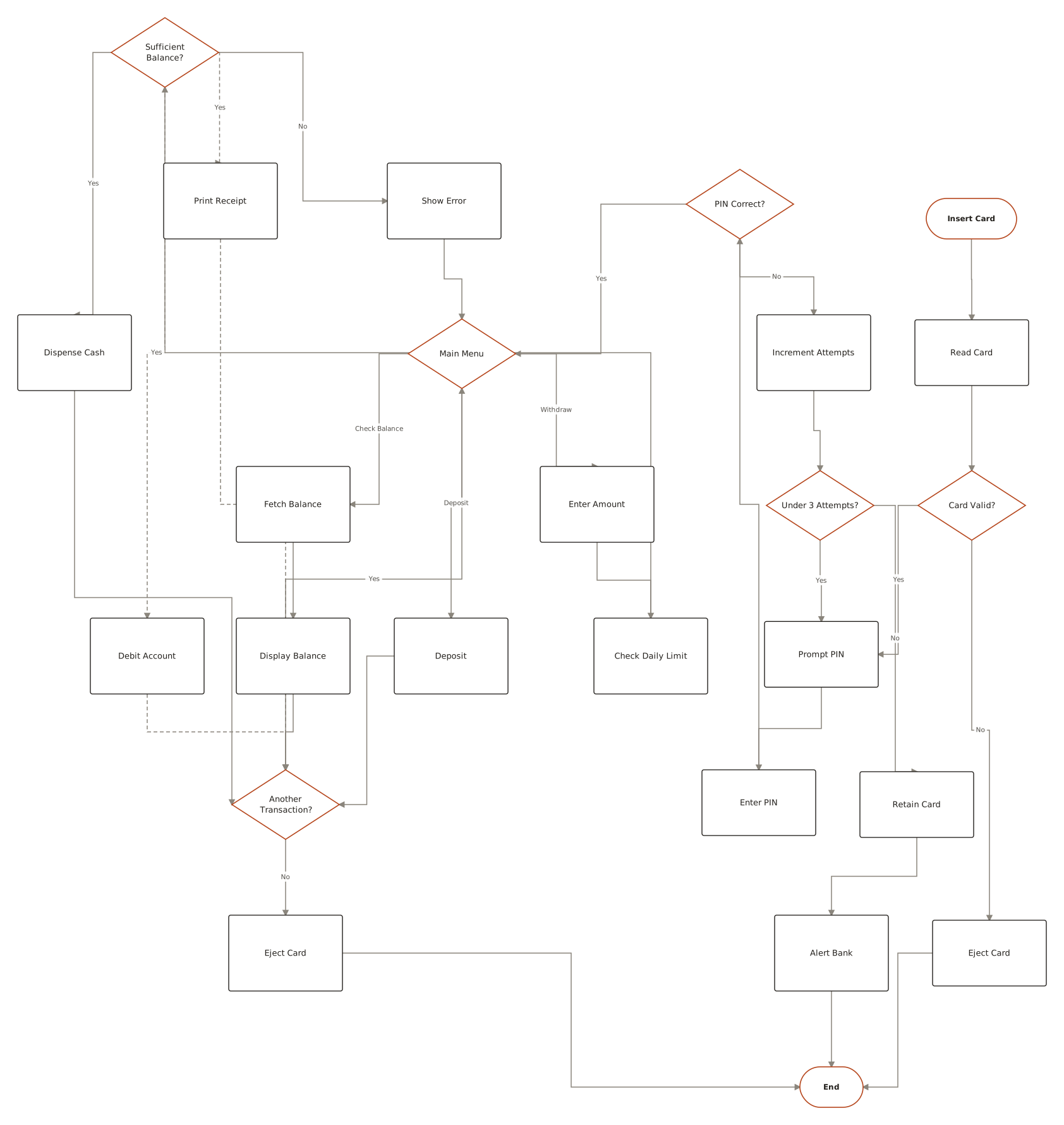
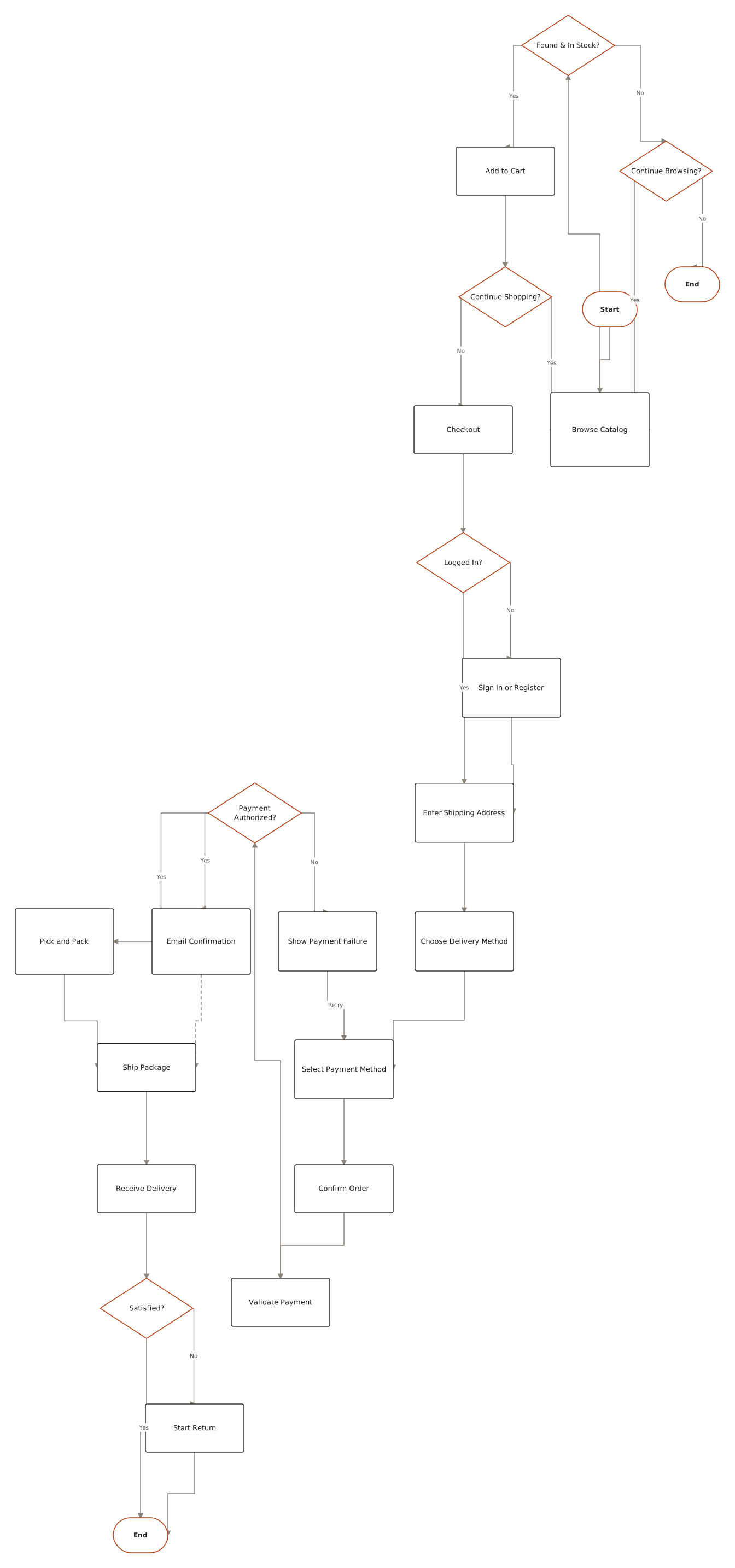
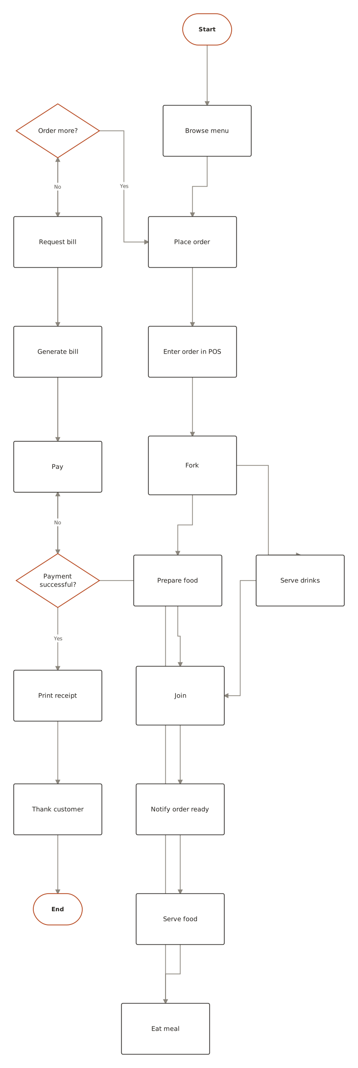
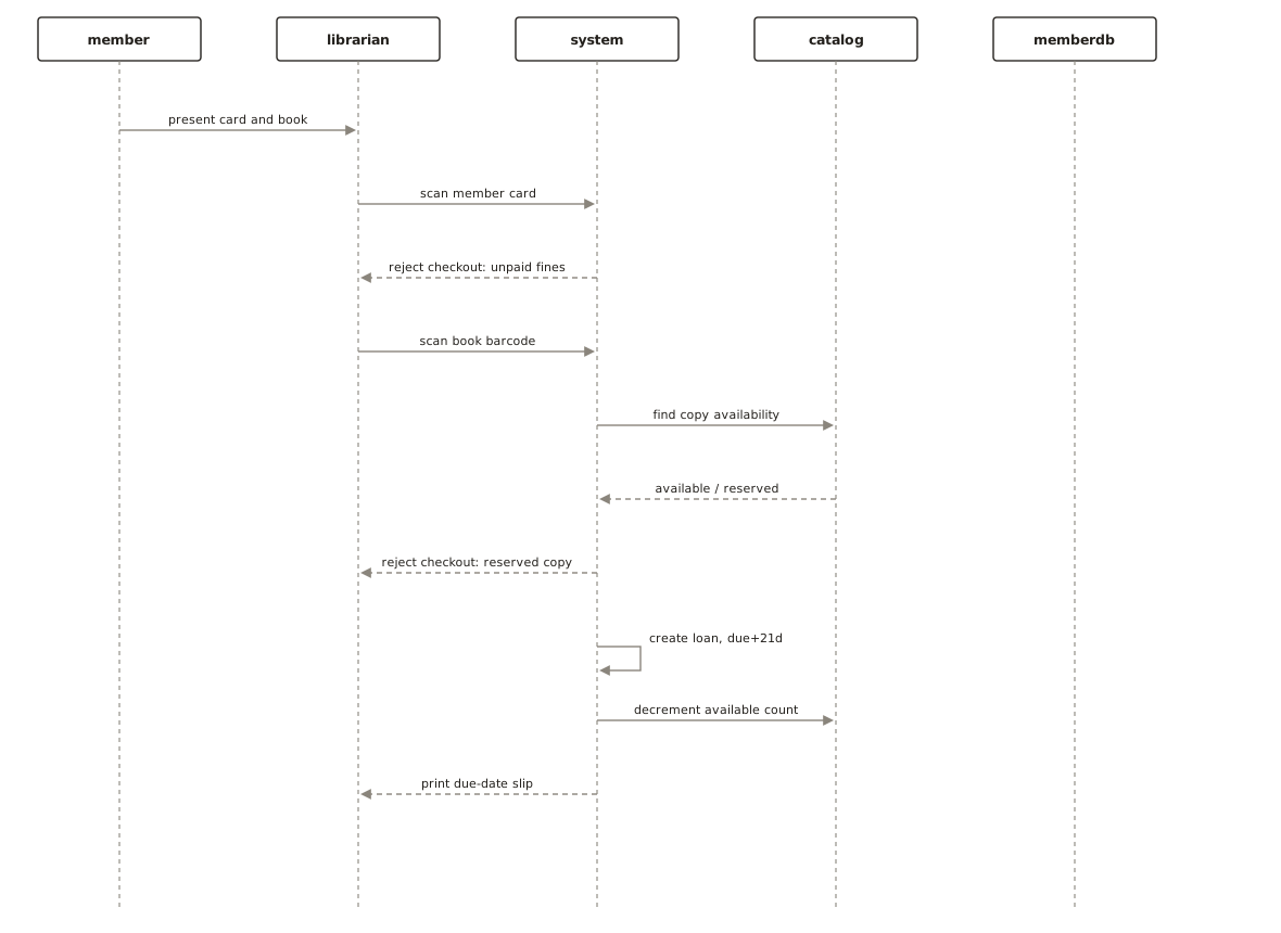
A use case diagram scopes the goals; the flow inside each goal is an activity or sequence diagram. These gallery diagrams show the “inside” of several use cases above — each was generated from a plain-English description.
Frequently asked questions
What is a use case diagram example?
A use case diagram example is a small UML model showing one system as a named box, the roles that use it as stick figures outside the box, and the goals they can achieve as ovals inside it. The ATM diagram on this page is the classic example: a Customer actor linked to Withdraw cash, Check balance, Deposit funds and Transfer money, all of which «include» Authenticate with PIN.
What are the three main elements of a use case diagram?
Actors (who), use cases (what goals) and the relationships between them (associations, «include», «extend», generalization). The system boundary is the fourth element most diagrams draw, but it is a frame rather than a modelling construct.
What is the difference between include and extend in the examples?
«include» is mandatory: Withdraw cash always includes Authenticate with PIN. «extend» is conditional: Print receipt extends Withdraw cash only if the customer asks for one. The arrow direction differs too — «include» points from base to included case, «extend» from the extension to the base.
How many use cases should a use case diagram have?
Enough to show every goal a stakeholder cares about and no more. The examples here have 8–11; past roughly 15 the diagram stops being readable and should be split by subsystem or by actor.
Can an external system be an actor?
Yes. The Bank system in the ATM example, the Payment gateway in the online shopping and airline examples and the Maps service in the ride-hailing example are all software actors. If your system sends it messages and does not control it, it is an actor.
Do use case diagrams show the order of steps?
No. A use case diagram has no time axis; it shows which goals exist and who can trigger them. The order of steps inside a goal belongs in an activity diagram or a sequence diagram — see the gallery links above for the ATM and online-shopping flows.
What is actor generalization in a use case diagram?
A hollow-triangle arrow from a specialised actor to a general one, meaning the specialised actor inherits every association of the general actor. In the online shopping example, Registered customer generalizes Customer and adds Track order and Write review.
Can I generate a use case diagram with ChartCraft?
Not natively — ChartCraft draws flowcharts, activity, sequence, state, class, ER, BPMN and architecture diagrams from text. The eight diagrams on this page were composed by hand in UML notation. For the behaviour inside any use case, describe it in plain English in the activity diagram generator or the sequence diagram generator.